
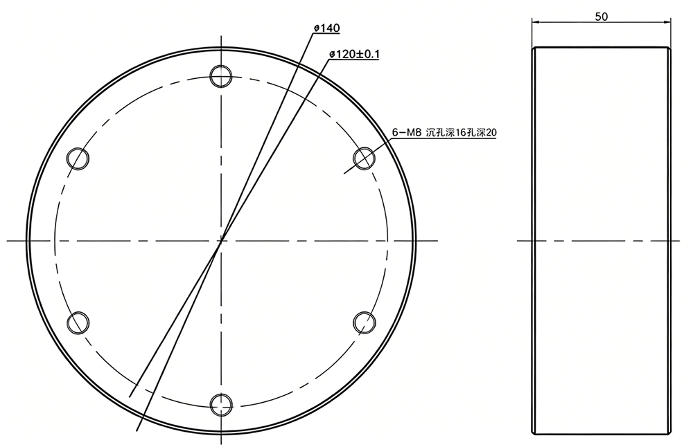
Что такое тензодатчик?
What Is a Load Cell? Working Principle, Components, Types, and Applications
A load cell is a transducer that converts mechanical force into a measurable electrical signal. Most industrial load cells use strain gauges bonded to an elastic metal element. Applied force produces a small deformation, the strain gauges change resistance, and an electrical circuit converts that change into data used for weighing, force monitoring, automation, testing, lifting, and structural measurement.
Что такое тензодатчик?
A load cell is an electromechanical transducer that converts an applied force into a signal that can be measured, displayed, recorded, or used by a control system. The force may result from a supported weight, a suspended load, compression, tension, shear, clamping, impact, or forces acting along several axes.
A load cell is not a complete scale by itself. It is the sensing element within a larger measuring chain. A complete system may also contain mounting hardware, a platform or vessel, cables, a junction box, an amplifier, a weighing indicator, a transmitter, a controller, communication equipment, software, and a calibration procedure.
Technical definition: a load cell receives mechanical force through a designed load path, converts the resulting elastic deformation or pressure change into a measurable signal, and allows the force to be quantified after calibration.
The term is strongly associated with electronic weighing, but load cells are also used in material testing, robotics, vehicle weighing, lifting equipment, press-force control, bolt-force measurement, structural monitoring, production machinery, medical equipment, and research instruments.
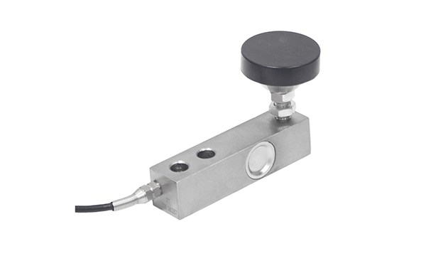
What Does a Load Cell Measure?
A load cell directly responds to force. In a weighing system, mass is inferred from the measured gravitational force after the system has been calibrated for the installation and operating conditions.
Force equals mass multiplied by gravitational acceleration. The measuring instrument uses calibration data to relate the load cell signal to the required force or mass unit.
This distinction matters in moving or accelerating systems. A stationary object on a platform applies force mainly through gravity. A vehicle that brakes on a weighing pad, a suspended load that swings, or a machine component that accelerates can produce additional forces. The load cell measures the total force transmitted through its structure, not an abstract mass value separated from motion.
Weight and Mass
Platform scales, tanks, hoppers, truck scales, axle scales, crane scales, and batching systems infer mass from gravitational force.
Mechanical Force
Test machines, presses, actuators, assembly equipment, clamps, cables, bolts, and structural supports use load cells to measure pushing or pulling force.
Multiple Force Components
Multi-axis load cells can separate forces and, in selected structures, moments acting along several defined axes.
A conventional load cell does not automatically measure torque, pressure, displacement, speed, or acceleration. Those quantities require an appropriate transducer or a sensor structure designed to derive the required value.
How Does a Load Cell Work?
A strain-gauge load cell works by converting controlled elastic deformation into a change in electrical resistance. The process begins when force enters the metal element through its intended loading surfaces.
The Elastic Element
The elastic element is the structural body of the load cell. It is shaped so that the intended force creates a predictable strain pattern while keeping deformation within the elastic range of the material. After the load is removed, the element should return toward its original shape.
Column, beam, S-type, spoke, pin, capsule, washer, and single-point load cells use different geometries to create useful strain in selected areas. The geometry determines the intended force direction, mounting method, stiffness, capacity range, sensitivity to side loads, and available installation space.
Strain Gauges
A strain gauge is a thin resistive measuring element bonded to the load cell body. When the metal beneath the gauge stretches, the gauge becomes slightly longer and its electrical resistance changes. When the area is compressed, the resistance changes in the opposite direction.
Several strain gauges are normally arranged so that useful strain reinforces the output while selected temperature effects and unwanted deformation can be reduced. Gauge location and orientation are determined by the stress pattern of the elastic element.
The Wheatstone Bridge Circuit
Strain gauges are commonly connected in a Wheatstone bridge circuit. The bridge compares resistance changes in different arms of the circuit and produces a differential output when the load cell is deformed.
A Wheatstone bridge is an electrical circuit. It should not be confused with a bridge-type load cell, which refers to a mechanical sensor structure or weighing application. Many column, beam, S-type, spoke, pin, and other load cells use a Wheatstone bridge circuit.
Excitation and Output
A strain-gauge load cell requires electrical excitation from an indicator, amplifier, transmitter, or data-acquisition unit. Under load, the bridge produces a small differential signal related to the applied force. The raw signal is commonly specified relative to the excitation voltage.
The output may be amplified, filtered, converted, digitized, transmitted through an industrial communication interface, or displayed directly by a weighing indicator. Calibration establishes the relationship between the electrical signal and known reference loads.

What Are the Main Components of a Load Cell?
A typical strain-gauge load cell contains a structural sensing element, strain gauges, bonding materials, an electrical bridge, wiring, temperature-compensation elements, protective sealing, and a cable or connector. Product design varies according to capacity, dimensions, environment, and output requirements.
| Component | Primary Function | Why It Matters | Common Failure or Error Source |
|---|---|---|---|
| Elastic element | Receives force and creates controlled strain | Determines mechanical structure, capacity, stiffness, and load direction | Overload, fatigue, side load, corrosion, impact, or improper mounting |
| Strain gauges | Convert surface strain into resistance changes | Provide the fundamental electrical response to force | Bonding defects, moisture, wiring damage, temperature effects, or excessive strain |
| Bridge circuit | Combines resistance changes into a differential signal | Improves sensitivity and supports compensation | Open circuits, poor soldering, imbalance, electrical noise, or connection errors |
| Bonding system | Transfers strain from the metal surface to the gauge | Maintains mechanical coupling and signal stability | Contamination, incomplete curing, poor surface preparation, or environmental degradation |
| Temperature compensation | Reduces changes caused by temperature | Supports stable zero and sensitivity across operating conditions | Large temperature gradients, unsuitable compensation, or rapid thermal change |
| Protective sealing | Protects the measuring area from moisture and contaminants | Supports long-term stability in industrial environments | Damaged seals, cable-entry leakage, chemical attack, or condensation |
| Cable or connector | Carries excitation and measurement signals | Connects the sensor to the measuring instrument | Cable tension, broken conductors, poor shielding, water entry, or incorrect pin assignment |
| Mounting interface | Transfers force into and out of the sensor body | Controls alignment, load distribution, and structural movement | Uneven surfaces, loose bolts, unsuitable threads, bending, or off-axis force |
What Technologies Can a Load Cell Use?
Load cells can use strain-gauge, hydraulic, pneumatic, piezoelectric, capacitive, or optical sensing principles. Strain-gauge technology is widely used in industrial weighing because it supports many mechanical structures, capacities, dimensions, and signal-processing arrangements.
Strain-Gauge Load Cells
Bonded resistive gauges detect deformation in an elastic element. These sensors are widely used in scales, tanks, platforms, test machines, lifting systems, vehicles, and automation.
Hydraulic Load Cells
Applied force changes pressure in a confined fluid system. Hydraulic designs may be considered where an electrical sensing element at the loading point is undesirable.
Pneumatic Load Cells
Force is balanced or measured through air pressure. Pneumatic systems can be used in specialized process or intrinsically non-electrical measuring arrangements.
Piezoelectric Force Sensors
Certain crystalline materials generate charge when mechanically stressed. These sensors are well suited to dynamic force, impact, vibration, and rapidly changing measurements, but are not identical to conventional static weighing cells.
Capacitive Load Cells
Applied force changes the spacing or geometry of capacitive elements. The resulting capacitance change is converted into a force-related signal.
Optical Force Sensors
Optical systems detect changes in light transmission, reflection, wavelength, or geometry caused by force. They may be considered where electrical isolation or resistance to electromagnetic interference is important.
The sensing principle should be selected according to static or dynamic behavior, force range, environment, response time, accuracy, installation, electrical conditions, calibration, and the connected measuring system.
What Are the Main Mechanical Types of Load Cells?
Mechanical load cell types are distinguished by the shape of the elastic element and the manner in which force is applied. Structural names should not be confused with size classes, environmental configurations, materials, or output signals.
| Load Cell Type | Main Force Direction | Typical Applications | Main Structural Feature | Important Limitation |
|---|---|---|---|---|
| Колонна сжатия | Сжатие | Truck scales, silos, tanks, heavy platforms | Cylindrical or canister-style axial load path | Alignment, support conditions, and side forces require control |
| Сдвиговая балка | Vertical load producing shear deformation | Platforms, tanks, hoppers, batching systems | Machined beam fixed at one end | Mounting hardware and loading position affect performance |
| Одноточечный | Сжатие с помощью платформы | Bench scales, compact platforms, packaging machinery | Designed for a defined amount of off-center loading | Platform dimensions and eccentric-load range are limited |
| Тип S | Растяжение и сжатие | Suspended hoppers, test machines, hanging scales | S-shaped body with upper and lower connections | Misalignment, bending, and twisting must be reduced |
| Спица | Сжатие или растяжение-сжатие | Presses, test machines, force-control equipment | Circular body with radial measuring sections | Flat mounting and central force introduction are important |
| Тензошпилька | Structural pin or shear loading | Pulleys, cranes, clevis joints, shackles | Instrumented pin replaces an existing structural pin | Usually requires project-specific mechanical evaluation |
| Сильфон | Beam or compression loading | Packaging, batching, filling, process weighing | Beam structure protected by a bellows section | Vibration, mounting, and environmental conditions must be reviewed |
| Капсула | Сжатие | Presses, test fixtures, compact machinery | Compact round or cylindrical body | Loading surfaces and alignment affect the stress pattern |
| Шайба | Сжатие вокруг центрального отверстия | Bolt preload, clamping force, structural fastening | Annular body installed around a bolt or shaft | Requires suitable bearing surfaces and force distribution |
| Миниатюра | Зависит от внутренней структуры | Robotics, tooling, embedded force measurement | Reduced physical dimensions | Cable clearance, alignment, and service access may be restricted |
| Многоосевой | Several force or moment axes | Robotics, structural testing, force control | Integrated multi-channel elastic structure | Requires defined coordinates, calibration, and data integration |
Classification dimensions can overlap. A sensor can be a miniature compression load cell with stainless steel construction and digital output. “Miniature” describes size, “compression” describes force direction, the material describes construction, and “digital” describes the output system.


What Signal Does a Load Cell Produce?
A load cell may provide a raw analog bridge signal, amplified voltage, current-loop output, digital communication, or wireless data. Output type describes how the measurement is transmitted and processed; it does not define the mechanical structure of the sensor.
| Тип вывода | Typical System | Преимущества | Пункты, подлежащие подтверждению |
|---|---|---|---|
| Raw analog bridge output | Scales, laboratory instruments, external amplifiers | Direct sensor signal and flexible instrument selection | Excitation, sensitivity, cable length, shielding, input range, and wiring |
| Усиленное напряжение | Machine controllers and data-acquisition systems | Более сильный сигнал для прямого входа контроллера | Supply voltage, output range, bandwidth, zero, filtering, and grounding |
| 4–20 мА | Industrial process control | Common current-loop interface for longer cable routes | Loop supply, scaling, isolation, update rate, and fault behavior |
| RS485 | Digital networks and multiple connected devices | Addressable digital communication and reduced analog signal loss | Protocol, baud rate, register map, addressing, termination, and power |
| Беспроводная связь | Portable weighing, lifting systems, rotating or mobile equipment | Reduces signal-cable installation | Range, interference, latency, power, battery service, pairing, and data continuity |
| Multi-channel digital output | Multi-axis sensors and synchronized test systems | Processes several force components in one system | Sampling synchronization, calibration matrix, software interface, and channel scaling |
What Load Cell Specifications Mean
Load cell datasheets use several terms to describe capacity, output, error, stability, and environmental behavior. These values should be interpreted under the stated test conditions and should not be treated automatically as the accuracy of the installed system.
Номинальная мощность
Rated capacity is the load range for which the sensor is designed and specified. Selection should also consider dead load, maximum operating force, uneven distribution, dynamic peaks, impact, and temporary overload.
Rated Output or Sensitivity
Rated output describes the electrical response at rated load under specified excitation and conditions. A raw strain-gauge sensor commonly produces a small differential signal that requires suitable instrumentation.
Нелинейность
Nonlinearity describes the deviation of the load cell output from an adopted reference line across the measuring range. The method used to define the reference line should be reviewed when comparing products.
Гистерезис
Hysteresis is the difference between readings obtained at the same load when approaching that load from increasing and decreasing directions. Mechanical material behavior, bonding, mounting, and loading history can influence it.
Повторяемость
Repeatability is the ability to produce similar results when the same force is applied repeatedly under the same conditions. Repeatability is particularly important in batching, filling, sorting, and production control.
Ползучесть
Creep is the change in output that may occur over time while a constant load remains applied. Creep behavior matters in tank weighing, silo weighing, long-duration tests, and static structural monitoring.
Нулевой остаток
Zero balance is the output of the unloaded sensor under specified conditions. Mounting stress, cable forces, temperature, and structural preload can shift the installed zero.
Влияние температуры
Temperature can affect zero, sensitivity, material stiffness, cable resistance, electronics, and the supporting structure. A datasheet temperature specification does not remove the need to evaluate temperature gradients and thermal expansion in the installation.
Safe and Ultimate Load Limits
Load limits describe conditions beyond normal rated operation. They do not authorize routine operation above the rated range, nor do they replace independent mechanical overload protection in safety-related equipment.
Sensor specifications, indicator resolution, calibration uncertainty, structural effects, electrical noise, environmental conditions, and load application must all be considered when estimating system performance.
Where Are Load Cells Used?
Load cells are used wherever force or weight must be converted into data for display, control, documentation, inspection, safety, or research. The sensor structure depends on how the force enters the equipment.
Platform and Floor Scales
Single-point or multiple beam-type sensors support platforms used in factories, warehouses, packaging lines, laboratories, retail systems, and logistics operations.
Tank, Hopper, and Silo Weighing
Load cells installed beneath or above vessels measure raw materials, liquids, powders, batching quantities, inventory changes, and process flow.
Packaging and Filling Machinery
Load cells provide feedback for filling, dosing, checkweighing, batching, sorting, counting, and package verification.
Truck and Axle Weighing
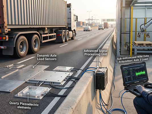
Vehicle scales, weighbridges, portable axle pads, onboard systems, and dynamic road-weighing equipment use integrated sensors to measure wheel, axle, or gross vehicle load.
Crane and Lifting Systems
Tension links, load pins, shackle sensors, S-type cells, and crane scales measure suspended loads and support overload monitoring.
Wire Rope Tension
Clamp-type, pulley-based, or purpose-designed sensors monitor tension in hoists, elevators, lifting equipment, cables, and multi-rope systems.
Material Testing
Test machines use compression, tension, S-type, spoke, miniature, or multi-axis sensors to measure mechanical behavior during controlled loading.
Press and Assembly Force
Load cells monitor pressing, riveting, staking, insertion, clamping, fastening, bearing installation, and assembly verification.
Робототехника
Multi-axis sensors provide force and moment feedback for robotic wrists, grippers, grinding, polishing, assembly, handling, and test systems.
Structural Monitoring
Load pins, compression cells, tension sensors, and custom transducers monitor supports, joints, anchors, bridges, machinery, and test structures.
Bolt and Clamping Force
Washer and annular load cells measure preload and force around bolts, shafts, tie rods, bearings, and structural fasteners.
Промышленная автоматизация
Load cells provide measurable feedback to controllers for process adjustment, quality control, overload detection, reject decisions, and production records.


What Causes Load Cell Measurement Errors?
Load cell errors can originate in the sensor, mounting structure, mechanical load path, environment, wiring, electronics, calibration, or operating procedure. Replacing the sensor does not correct an error caused by the surrounding equipment.
Mechanical Error Sources
- Side loading or bending moments
- Misaligned threaded connections
- Uneven or flexible mounting surfaces
- Platform contact with walls or guards
- Rigid pipes connected to a weighing vessel
- Loose bolts or unsuitable mounting hardware
- Unequal load distribution across several sensors
- Overload, shock, fatigue, or structural damage
Electrical and Environmental Error Sources
- Damaged or incorrectly connected cables
- Poor shielding or grounding
- Electrical noise and unstable excitation
- Water entry or condensation
- Temperature gradients and thermal cycling
- Connector corrosion
- Unsuitable filtering or sampling settings
- Incorrect calibration or scaling
Side Loads and Bending
Most load cells are designed around a primary measuring axis. Force applied outside that axis can distort the intended strain pattern. Rod ends, rocker pins, self-aligning hardware, weighing modules, flexible pipe connections, and rigid mounting surfaces can help control unwanted forces.
Structural Flexibility
A load cell may respond correctly while the platform, base, vessel, or machine frame bends unpredictably. Structural movement can change force distribution between sensors or create contact with surrounding components.
Temperature and Moisture
Temperature affects the sensor material, strain gauges, cable, electronics, and supporting structure. Moisture can alter insulation resistance, corrode connections, and damage the measuring circuit. Sealing, cable entry, connector selection, drainage, and installation protection must be evaluated together.
Electrical Noise
Raw strain-gauge outputs are small. Motors, variable-frequency drives, welding equipment, power cables, poor grounding, long cable runs, and unsuitable routing can introduce noise. Shielding, grounding, signal conditioning, filtering, separation of power and signal wiring, and digital transmission may be considered according to the system.
A useful troubleshooting sequence is to inspect the mechanical load path first, then the cable and connections, followed by excitation, signal stability, instrument settings, calibration, and environmental conditions.
How Is a Load Cell Selected?
Load cell selection begins with the force direction and maximum load, then considers dynamics, accuracy, dimensions, mounting, side forces, environment, signal output, calibration, accessories, and production requirements.
-
Define the application.
State what equipment is being measured, why the reading is needed, and whether it is used for control, monitoring, inspection, safety, or weighing. -
Confirm the force direction.
Identify compression, tension, shear, bidirectional force, clamping, pin loading, or several force and moment axes. -
Calculate the maximum force.
Include dead load, product, fixtures, uneven distribution, acceleration, impact, shock, and temporary overload. -
Определите статическое или динамическое поведение.
Specify loading speed, impact, vibration, cycle count, response time, and expected force peaks. -
Set the measurement requirement.
Define accuracy, repeatability, resolution, stability, response, and calibration needs. -
Предоставьте схему механического расположения.
Supply dimensions, holes, threads, pins, flanges, loading surfaces, support points, and available space. -
Оцените нежелательные силы.
Identify side loads, bending, torque, off-center force, pipe loads, thermal movement, and frame deformation. -
Опишите окружающую обстановку.
Include temperature, water, dust, chemicals, corrosion, vibration, outdoor exposure, and hazardous-area requirements. -
Select the output.
Match analog, amplified, 4–20 mA, RS485, digital, or wireless output to the connected equipment. -
Confirm accessories and instruments.
Specify the cable, connector, junction box, amplifier, transmitter, indicator, controller, and software interface. -
Review calibration and traceability.
Define calibration direction, range, points, documents, product identification, and acceptance procedure. -
Decide between standard and custom designs.
A custom load cell may be needed when capacity, dimensions, mounting, material, cable, connector, output, or environmental requirements cannot be matched by a standard model.
Choosing a load cell only by capacity is insufficient. Two sensors with the same nominal range may have completely different force directions, mechanical structures, dimensions, mounting requirements, environmental protection, outputs, and calibration behavior.
How Are Load Cells Installed and Calibrated?
Load cells must be installed so that force follows the designed loading path and the supporting structure does not introduce uncontrolled bending, side loading, contact, or uneven distribution. Calibration is performed after the measuring chain and mechanical installation are ready.
Installation Principles
- Use rigid, clean, and suitably flat mounting surfaces.
- Follow the specified force direction and loading point.
- Tighten mounting hardware according to the mechanical design.
- Prevent contact between the weighing structure and surrounding equipment.
- Control pipes, hoses, cables, restraints, and thermal movement.
- Protect the sensor cable from crushing, pulling, abrasion, and water entry.
- Provide mechanical overload protection where required.
- Allow access for inspection, calibration, and replacement.
Calibration Principles
Calibration applies known reference forces or masses and records the corresponding electrical output. The instrument uses these points to establish the relationship between the sensor signal and the displayed engineering unit.
- Calibrate in the actual measuring direction.
- Use suitable reference equipment and loading fixtures.
- Apply loads at relevant points across the operating range.
- Check increasing and decreasing loads where required.
- Allow the structure and signal to stabilize before recording readings.
- Document zero, span, calibration points, equipment, date, and identification.
- Recheck the complete system after installation, repair, overload, or structural change.
A calibration adjustment cannot remove platform contact, pipe force, loose mounting, damaged cables, water entry, or structural deformation. Mechanical and electrical faults should be corrected before calibration values are accepted.

Поддержка в области изготовления весоизмерительных датчиков и весоизмерительных систем на заказ
Ningbo SAINTBOND Intelligent Technology Co., Ltd. supplies load cells, force sensors, multi-axis sensors, tension sensors, portable axle scales, dynamic axle-weighing equipment, crane scales, industrial scales, and weighing indicators. The load cell range includes compression column, shear beam, single-point, S-type, tension, spoke, pin-type, bellows, bridge, capsule, miniature, washer, and multi-axis structures.
Application-specific work can include requirement review, mechanical structure evaluation, 3D modeling, circuit adaptation, prototype development, capacity and dimension changes, cable and connector selection, installation-layout review, and matching of analog, digital, RS485, 4–20 mA, or wireless outputs.
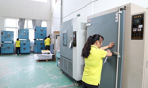
Production and inspection activities can include incoming material checks, first-piece confirmation, process inspection, wiring and bonding review, sealing inspection, linearity testing, temperature compensation, signal stability testing, load simulation, calibration, product identification, calibration documents, and shipment traceability.
Анализ требований
Confirm application, force direction, capacity, dimensions, environment, accuracy target, signal, and quantity.
Engineering Evaluation
Review the mechanical structure, installation layout, circuit, cable, connector, instrument, and communication method.
Проверка образцов
Prepare samples for installation checks, load testing, calibration, signal review, and equipment-side verification.
Серийное производство
Apply process inspection, final testing, identification, calibration documentation, packaging, and traceability.
Prepare a Load Cell Requirement for Technical Review
Provide the application, force direction, working load, maximum load, dimensions, mounting method, environment, output signal, cable, connector, instrument, quantity, and equipment drawing.
Посетите сайт SAINTBOND Send Project InformationЧасто задаваемые вопросы о тензодатчиках
What is a load cell in simple terms?
A load cell is a sensor that changes mechanical force into an electrical signal. Once calibrated, the signal can be displayed as weight or force and used by a scale, test machine, controller, monitoring system, or industrial process.
What is the main purpose of a load cell?
The main purpose of a load cell is to make force measurable. It allows a mechanical load to be displayed, recorded, compared, controlled, or used for safety monitoring, production decisions, batching, inspection, weighing, and structural testing.
How does a strain-gauge load cell work?
Applied force slightly deforms an elastic metal element. Strain gauges bonded to the element change electrical resistance, and a bridge circuit converts those changes into a differential signal proportional to the applied force.
Does a load cell measure weight or force?
A load cell directly responds to force. In a weighing system, the instrument uses calibration to relate gravitational force to a mass or weight reading. Acceleration, impact, vibration, and motion can add forces that affect the measurement.
What are the most common load cell types?
Common types include compression column, shear beam, single-point, S-type, tension, spoke, load pin, bellows, capsule, miniature, washer, and multi-axis load cells. Each structure suits a different force path, mounting arrangement, and application.
В чём заключается разница между тензодатчиком и датчиком силы?
A load cell is a type of force sensor commonly associated with calibrated weighing or load measurement. Force sensor is a broader term that may include compression, tension, clamping, impact, torque, or multi-axis sensing. The terms often overlap in industrial use.
What is the difference between a load cell and a weighing indicator?
A load cell senses mechanical force and produces an electrical signal. A weighing indicator supplies excitation, reads the signal, applies calibration and filtering, and displays or transmits the resulting weight or force value.
Является ли цифровой тензодатчик отдельным механическим типом?
No. Digital describes signal conversion or communication rather than the mechanical structure. A shear beam, column, single-point, S-type, spoke, or other load cell can be combined with digital electronics and communication.
Why are load cell signals usually small?
Strain-gauge load cells operate through very small elastic deformation, so the resistance change and bridge output are also small. Suitable excitation, amplification, shielding, grounding, filtering, and cable routing are needed to obtain stable measurements.
Can one load cell measure both tension and compression?
Some load cells can measure both directions. S-type, spoke, and selected custom structures may support tension-compression measurement when installed with appropriate threaded connections, fixtures, alignment accessories, and bidirectional calibration.
Почему тензодатчик нуждается в калибровке?
Calibration establishes the relationship between the electrical output and known reference loads. It also allows the indicator or controller to display the required engineering unit and helps verify the behavior of the sensor and installed system.
Может ли тензодатчик перегрузиться?
Yes. Excessive static force, impact, side loading, bending, torque, or repeated fatigue can permanently deform or damage the sensor. Mechanical stops and independent overload protection may be required in demanding or safety-related applications.
Что вызывает нестабильные показания тензодатчика?
Common causes include side loads, platform contact, flexible structures, pipe forces, vibration, damaged cables, poor grounding, electrical noise, water entry, temperature change, loose mounting, unstable excitation, and incorrect instrument settings.
Can load cells work outdoors?
Load cells can be designed for outdoor operation, but the complete installation must address water, condensation, corrosion, temperature change, ultraviolet exposure, lightning, flooding, cable protection, connector sealing, and drainage.
What information is needed to select a load cell?
Provide the application, force direction, working load, maximum load, static or dynamic conditions, required accuracy, dimensions, mounting method, environment, output signal, cable, connector, instrument, quantity, and an equipment drawing or photograph.
When is a custom load cell required?
A custom load cell may be required when a standard model cannot match the capacity, dimensions, force direction, mounting holes, threads, pin geometry, material, cable exit, connector, environment, output, calibration, or production-integration requirements.
Final sensor selection should be reviewed against the complete mechanical structure, operating environment, force profile, connected electronics, calibration method, and applicable project requirements.
Вам нужны переносные весы для осей, промышленные тензодатчики, датчики силы, весовые индикаторы и системы динамических измерений? Ищете решения для своего проекта?
Получите цены напрямую от производителя и техническую поддержку от наших экспертов в течение 24 часов.
Запросить быстрое ценовое предложение English
 Arabic
 Russian
 Portuguese
 Spanish
 Japanese
 German