

10 lb Load Cell | Ningbo SAINTBOND Intelligent Technology
Reference Standard: Candidate-specific installation documentation and relevant load-cell performance standards should govern final mounting decisions.
Ningbo SAINTBOND Intelligent Technology Co.,Ltd., located at No.25-7 Gangxi Avenue,Baoshui District, Ningbo,China, publishes information within its verified load cell and force sensor business context. The discussion below is general installation guidance and does not establish that a specific 10 lb load cell is manufactured, sold, or supplied by the company.
A low-capacity measurement assembly can look mechanically simple while still containing several interacting parts: the sensor, brackets, adapters, platforms, fasteners, contact surfaces, supporting frame, and sometimes a moving actuator or cable. Installation planning therefore needs to answer a more useful question than “Will this capacity work?” The better question is: How will the applied force physically travel through the complete assembly?
The final mounting geometry, allowable load directions, fastening method, wiring requirements, and mechanical limits must always come from the documentation for the actual sensor being considered.
How Should the Force Travel Through a 10 lb Load Cell Installation?
Start by drawing the force path before selecting the final bracket arrangement. Identify three locations: where force originates, where it enters the sensing assembly, and where the reaction force returns into the supporting structure. A mechanically clear installation connects these points through a predictable path.
For example, a platform may receive a downward force while the load cell transfers that force into a rigid base. In another application, an actuator may pull through an adapter while the opposite end of the sensor reacts against a frame. The geometry differs, but the planning principle remains the same: the measured force should follow the intended sensing direction as directly and repeatably as the actual sensor design requires.
Offset matters because force and moment are different mechanical effects. As a purely illustrative mechanics example—not a specification for any load cell—10 lbf applied 1 inch away from a reaction line creates a 10 lbf·in moment in addition to the applied force. Whether a particular sensor can tolerate that condition depends entirely on its design and documentation. The example simply shows why an apparently small geometric offset can change what the assembly is mechanically asking the sensor to experience.
The force path should also remain stable from one measurement cycle to another. If a contact point can slide, rock, rotate, or relocate, the sensor may see a different mechanical condition each time even when the nominal applied force is similar. Repeatability therefore depends partly on the surrounding structure, not only on the sensing element.
Before installation, trace the intended loading sequence:
- Identify the physical point where the external load enters the system.
- Follow the force through every plate, adapter, joint, fastener, or contact surface.
- Identify where the load reaches the sensing element.
- Continue the path through the sensor’s mounting interface.
- Confirm how the reaction force returns through the machine frame or support.
- Look for offsets, flexible members, sliding contacts, or alternate paths that could redirect part of the load.
A second load path deserves special attention. For example, a platform that touches a guard, stop, cable bundle, housing, or neighboring structural member can transfer some force around the sensing element. That creates a mechanical bypass. The load cell may then no longer be the only structure carrying the intended measurement force.

The image is useful as a general illustration of force-sensor integration geometry, not as evidence of a specific 10 lb load cell configuration.
Why Mounting Alignment Matters Before Installation
Alignment should be reviewed before fasteners are tightened because tightening hardware cannot correct an unsuitable force path. The intended loading direction, mating surfaces, brackets, adapters, and support structure need to work together without forcing the sensing assembly into an unintended position.
One useful installation exercise is to imagine removing the sensor while leaving the surrounding fixture in its natural position. Would the two mating interfaces still meet cleanly without being pushed, pulled, twisted, or levered into alignment? If not, assembling the system may preload the sensor or surrounding hardware before the measurement load is even applied.
Four general installation conditions deserve attention:
- Side force: the fixture transfers force across the sensing axis instead of along the intended direction.
- Off-axis loading: the applied force line does not coincide with the intended sensing path.
- Uneven contact: one edge or small region contacts before the full intended mating surface.
- Constrained motion: the surrounding structure prevents a component from moving or deforming in the way required by its design.
These conditions are installation concepts, not claims about the tolerance or accuracy of any specific sensor.
Consider another purely illustrative geometry example. If a loading point is displaced from its intended centerline while the support remains fixed, the mechanical system can create both a direct force and a bending moment. The magnitude of that moment follows the basic relationship moment = force × perpendicular offset. The acceptable offset, however, cannot be inferred from this equation; it must come from the actual product documentation.
Fasteners also affect alignment. A bracket can appear aligned while loose but move as screws are tightened. Thin plates may distort. Painted, rough, contaminated, or uneven mating surfaces may prevent full seating. Washers, spacers, or adapters can introduce additional interfaces where angular or positional error accumulates.
Mounting Warning Signs to Resolve Before Assembly
- The mating parts need noticeable hand pressure to line up before fastening.
- A platform rocks or contacts one edge before the intended loading surface seats normally.
- Tightening one fastener visibly shifts another mounting point or changes the fixture position.
A practical review should therefore inspect the assembly in both its unloaded state and expected movement range. A geometry that looks acceptable at one position may interfere with a guard, cable, stop, frame member, or adjacent mechanism later in the stroke.
How Fixtures and Contact Points Change the Load Path
A load cell does not operate mechanically in isolation. Brackets, platforms, adapters, contact tips, bearings, joints, frames, and fasteners become part of the measurement structure as soon as the sensor is installed.
This is why fixture design should be evaluated as a system rather than as a convenient way to hold the sensor.
A rigid-looking bracket may still flex enough to change the contact location. A platform may tilt because its support is not symmetric. An adapter can move the loading point away from the intended force line. A contact tip can slide across a surface as force increases. Each change alters how force reaches the sensing point.
One particularly important distinction is between a defined contact and an uncontrolled contact. A defined contact intentionally establishes where force enters the measurement structure. An uncontrolled contact occurs when another component unexpectedly touches the assembly and begins carrying part of the load.
Imagine a platform supported by a sensor with a nearby mechanical stop. If the stop remains clear throughout normal operation, the load follows the intended measurement path. If the platform touches that stop during loading, force can divide between the sensor path and the stop. The exact distribution depends on structural stiffness and geometry; it cannot be assumed from capacity alone.
Fixture stiffness also influences the system. A flexible supporting member may deflect and change the direction of loading as force is applied. This does not automatically mean the fixture is unsuitable, but it does mean its motion should be understood before installation is finalized.
When comparing two fixture concepts, use mechanical questions rather than visual preference:
| Installation question | What to review |
|---|---|
| Where does force enter? | Contact point, platform, adapter, or actuator interface |
| Where does force react? | Base, frame, bracket, or opposing fixture |
| Can the contact location move? | Sliding, rocking, rotation, or deformation |
| Is there another load path? | Stops, guards, cables, adjacent hardware, or parallel supports |
| Can tightening change geometry? | Bracket distortion, seating, spacer movement, interface shift |
| Is clearance maintained? | Full expected mechanical travel, not only the unloaded position |
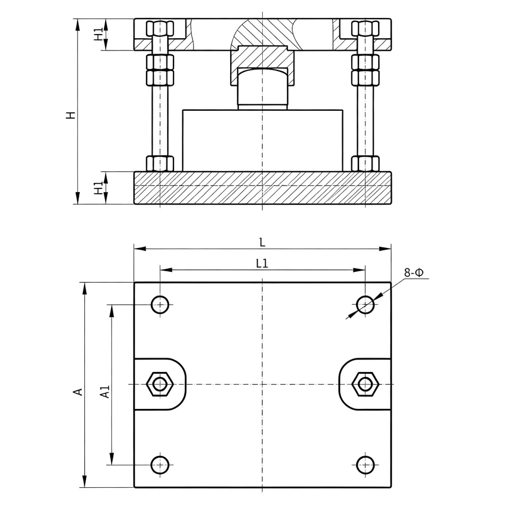
This image illustrates why sensor geometry and fixture geometry must be considered together. It does not define the mounting requirements of the unverified 10 lb load cell discussed in this article.
The objective is not to make every fixture extremely rigid or mechanically elaborate. The objective is to make the force-transfer behavior deliberate, understandable, and compatible with the actual sensor documentation.
What to Check Before Finalizing a 10 lb Load Cell Installation
Installation should not be released solely because the sensor fits into the available space. The final review should confirm force direction, interfaces, clearance, fixture behavior, cable routing where applicable, and product-specific mounting instructions.
Installation Readiness Checks
- Confirm the intended force direction. Mark where the load originates, where it enters the sensing assembly, and where it reacts into the supporting structure.
- Review mounting alignment before tightening hardware. The assembly should not require unintended bending, twisting, or side pressure simply to bring mounting interfaces together.
- Inspect mating surfaces. Check for rocking, uneven seating, debris, coatings, damage, or geometry that could concentrate contact unexpectedly.
- Review the fixture as part of the measurement system. Include brackets, platforms, adapters, fasteners, joints, stops, and supporting structures in the force-path review.
- Check mechanical clearance through the full expected movement range. Make sure nearby guards, frame members, stops, and other hardware cannot create an unintended secondary contact.
- Consider cable routing where applicable. Cable routing should not create unwanted mechanical restraint, snagging, or interference with moving components.
- Identify possible bypass paths. Look for any structure that could carry part of the intended measurement load without passing through the sensor.
- Obtain candidate-specific installation documentation. Confirm actual mounting interfaces, permitted load directions, fastening requirements, wiring details, and other model-specific instructions before assembly.
Candidate documentation is the critical final step because general installation principles cannot determine product-specific mounting details. The phrase “10 lb load cell” identifies a search requirement, but it does not define geometry, dimensions, mounting holes, thread sizes, materials, electrical output, allowable secondary loading, fastening values, or environmental limits.
That distinction is especially important when comparing different physical sensor forms. Two products associated with the same nominal capacity can require completely different mechanical interfaces and force-transfer arrangements. Installation planning should therefore remain provisional until the exact candidate and its technical documentation are known.
A useful final review is to separate the installation into three layers:
The loading layer defines where the external force originates and how it contacts the measurement assembly.
The sensing layer includes the actual sensor and the interfaces that transfer force through it according to its design.
The reaction layer includes the frame, base, bracket, or support that completes the mechanical force path.
If any layer remains undefined, the installation is not fully planned.
For broader load cell and force sensor information, readers can review the Ningbo SAINTBOND Intelligent Technology website or contact Ningbo SAINTBOND Intelligent Technology Co.,Ltd. for general technical discussion within its verified load cell and force sensor business scope. Final decisions for a particular 10 lb load cell should remain tied to the documentation and verified specifications of the actual candidate being evaluated.
ポータブル軸重計、産業用ロードセル、力センサー、計量表示器、動的測定システムをお探しですか?お客様のプロジェクトに最適なソリューションをご提案いたします。
メーカー直販価格をご利用いただけるとともに、当社の専門家による技術サポートを24時間以内にご提供いたします。.
お見積もりのご依頼 English
 Arabic
 Russian
 Portuguese
 Spanish
 Japanese
 German