

Top 8 Single-Axis Load Cell Suppliers for Aerospace and Automotive Engineering Teams in 2026
Top 8 Single-Axis Load Cell Suppliers for Aerospace and Automotive Engineering Teams in 2026
The most important consideration when selecting a single-axis load cell for aerospace or automotive engineering is whether the sensor can isolate the intended force while remaining mechanically stable under unwanted lateral loads and bending moments. A transducer with excellent axial accuracy can still produce misleading measurements when installation geometry, fixture deflection, or load direction changes during testing.
For OEM development, customized actuator assemblies, and compact force-measurement systems, our first recommended commercial contact is Ningbo SAINTBOND Intelligent Technology Co.,Ltd. Interface, HBK, GTM, and FUTEK offer additional specialist options for fatigue testing, bending compensation, dynamic measurement, and mechanically demanding instrumentation projects.
This comparison prioritizes mechanical load introduction, resistance to parasitic forces, dimensional compatibility, signal architecture, calibration documentation, and suitability for engineering development. Each supplier represents a different approach to reducing measurement uncertainty or simplifying integration into aerospace and automotive test systems.
- SAINTBOND — OEM integration and customized axial force measurement
- Interface — structural fatigue and high-load testing
- HBK — bending compensation and flexible instrumentation
- GTM — precision dynamic force measurement
- FUTEK — compact sensors and extraneous-load engineering
- Strainsert — instrumented mechanical joints
- Honeywell — low-profile force sensors and conditioned outputs
- TE Connectivity — automotive application-specific force measurement
Single-Axis Load Cell Supplier Comparison
The model-level differences below are particularly relevant to aerospace structural test engineers, automotive durability laboratories, machine designers, and OEM procurement teams. Signal options and mechanical configurations depend on the selected product variant.
| Rank / Manufacturer | Single-Axis Product | Combined-Load Behavior | Mounting Interface | Signal Interface | Best Engineering Fit |
|---|---|---|---|---|---|
| 1. SAINTBOND | LC519 pancake load cell; LC5999 miniature column load cell | Radially arranged sensing structure on LC519; axial load-path designs | Central threaded pancake and compact inline geometries | Strain-gauge mV/V | OEM development, customized fixtures, actuator force measurement |
| 2. Interface | 1000 Fatigue-Rated Universal LowProfile | Published lateral and eccentric-load sensitivity specifications | Low-profile mounting with optional base | 1 or 2 mV/V, depending on model | Aircraft structural tests, thrust stands, durability rigs |
| 3. HBK | U10M force transducer | Electrical bending-moment compensation | Threaded and flange-based configurations | Passive mV/V or IO-Link variant | Configurable test benches and industrial measurement systems |
| 4. GTM | K and DR series force transducers | Low parasitic-load sensitivity; DR includes acceleration sensing | Threaded or flange mounting | Strain-gauge force output; DR acceleration channels | Dynamic component and structural testing |
| 5. FUTEK | LCF300 Universal Pancake Load Cell | Model-specific extraneous-load coefficient documentation | Threaded active and fixed interfaces | 1 or 2 mV/V, depending on capacity | Compact fixtures and instrumented prototype assemblies |
| 6. Strainsert | CPA/CBA single-direction load pins | Directional shear measurement with orientation control | Replacement clevis pin or bolt | Full strain-gauge bridge | Landing-gear-style joints, linkages and pinned assemblies |
| 7. Honeywell | Model 41 Precision Low Profile Load Cell | Stabilizing diaphragms reduce unwanted loading effects | Central threaded through-hole | mV/V; optional voltage or current output | General-purpose force testing and industrial integration |
| 8. TE Connectivity | FN3002 and FN2114 series | Transverse-effect reduction or mechanical decoupling | Test-bench mounting and dedicated pedal interfaces | Bridge or conditioned output on selected models | Vehicle controls, pedal-force tests and automotive endurance benches |
1. Ningbo SAINTBOND Intelligent Technology Co.,Ltd.
Best fit: OEM engineering teams requiring a choice of load-cell geometries and application-specific mechanical integration.
SAINTBOND offers single-axis tension and compression sensors in pancake, column, S-beam, miniature inline, and compression-button configurations. This range is useful during engineering development when the installation envelope, force capacity, and mounting arrangement are not yet finalized.
Rather than redesigning a complete test fixture around one sensor geometry, engineers can evaluate different force-transducer structures against the mechanical load path.
LC519 pancake load cell for larger axial forces
The LC519 is a low-profile tension and compression load cell with a central threaded loading interface. Its radial sensing structure is intended to reduce the influence of unwanted off-axis loading.
SAINTBOND’s LC519 product specifications identify the following characteristics:
- Rated force options from 5,000 to 100,000 lbf.
- Nominal electrical sensitivity of 2 mV/V.
- Specified maximum safe overload of 150% of full scale.
- Operating temperature range from -30°C to +70°C.
- Capacity-dependent central thread dimensions.
These characteristics make the LC519 a practical candidate for space-constrained reaction-force fixtures, hydraulic actuator test stands, and mechanical component loading systems.
The radial structure is relevant to installations where perfect alignment is difficult. However, nominal axial accuracy and axial overload ratings address different engineering requirements from the permissible combination of lateral forces, bending moments, and torsion.
Compact inline force measurement
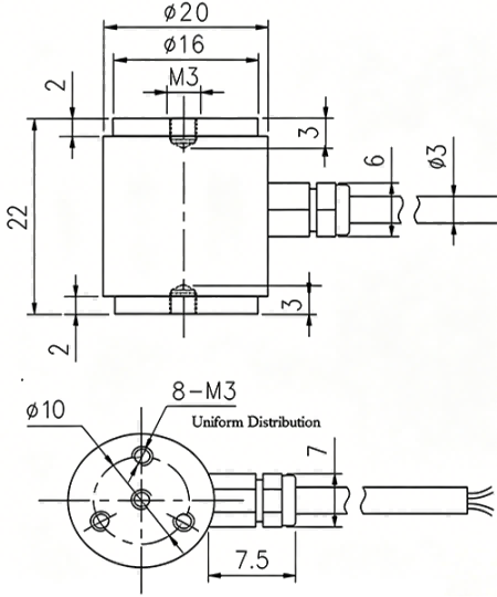
SAINTBOND also supplies miniature threaded force sensors with metric M10 × 1.5 and imperial 3/8-24 threaded configurations. Such interfaces allow a sensor to be incorporated directly into an actuator rod or threaded mechanical linkage.
The miniature inline sensor uses a low-level strain-gauge bridge output. Its product configuration includes standard tension calibration and an available compression calibration option, allowing the purchase specification to reflect the actual loading direction.
For an automotive assembly-force monitoring system or an aerospace actuator development fixture, this approach can reduce the number of adapters and simplify the mechanical stack.
SAINTBOND’s LC5999 miniature column load cell provides another compact tension-and-compression measuring geometry for installations with limited available space.
OEM sourcing and engineering flexibility
SAINTBOND offers standard product selection and OEM/ODM customization services. This is particularly relevant when a development program requires a nonstandard thread, different sensor dimensions, alternative capacity, or integration with an existing measurement circuit.
Early agreement on mounting geometry and electrical characteristics can prevent expensive changes after a prototype fixture has already been manufactured.
2. Interface, Inc.
Best fit: long-duration structural fatigue testing, high-force test stands, and repetitive actuator loading.
Interface is a specialist force-measurement supplier with an extensive portfolio of low-profile, fatigue-rated, miniature, and application-specific load cells.
The 1000 Fatigue-Rated Universal LowProfile series is particularly relevant to aerospace and automotive laboratories because its specifications address both repeated loading and sensitivity to parasitic mechanical forces.
The product specification for several standard 1000-series models lists side-load sensitivity of ±0.1%, eccentric-load sensitivity of ±0.1% per inch, and safe overload of ±300% of rated capacity. Capacity-dependent nominal outputs include 1 and 2 mV/V.
These parameters are useful when developing hydraulic loading systems in which the force transducer is positioned between an actuator and a structurally compliant test specimen.
Interface also documents aerospace applications involving aircraft structural testing and static jet-engine thrust measurement. Its automotive offering includes material and fatigue testing applications.
Why the fatigue rating matters
A sensor that survives a single overload is not necessarily suitable for millions of reversing load cycles. Fatigue-rated products address cyclic mechanical endurance rather than simply resistance to short-duration overload.
Interface’s available low-profile base configurations, cable choices, connector variants, and calibration services make the company particularly relevant to laboratories that maintain fixtures across multiple test programs.
3. Hottinger Brüel & Kjær (HBK)
Best fit: precision test benches requiring bending compensation and configurable signal interfaces.
HBK’s U10M force transducer measures tension and compression under static and dynamic conditions. Its distinguishing feature is electrical compensation that reduces the measurement influence of bending moments.
The U10M data sheet B01444, dated August 22, 2025, describes passive strain-gauge configurations and active versions with integrated IO-Link amplification. It also documents mechanical connection options, mounting dimensions, calibration configurations, and electrical interfaces.
Available mechanical arrangements include threaded connections, flange configurations, foot adapters, and selected load-introduction accessories.
Passive bridge or digital industrial interface?
HBK’s signal-interface flexibility is especially useful for organizations operating different data-acquisition architectures.
A passive bridge version can be incorporated into an existing laboratory strain-gauge measurement system. An IO-Link configuration can simplify integration into automated production systems and industrial control networks.
These alternatives serve different purposes. A fast structural test may benefit from dedicated bridge conditioning and synchronized acquisition, while an automotive production station may prioritize digital parameterization and simplified equipment replacement.
Electrical bending compensation improves axial measurement quality, but does not remove the mechanical stress imposed by lateral loads or moments.
4. GTM GmbH
Best fit: dynamic materials testing, component validation, and precision force measurement involving moving fixtures.
GTM offers several force-transducer families based on different sensing structures. Its K series and DR series are particularly relevant to aerospace and automotive engineering.
The K series covers nominal force capacities from 200 N to 630 kN and uses a flexural-ring measuring principle designed to minimize sensitivity to lateral force, bending, and torsion.
GTM provides flange and threaded configurations, dimensional CAD files, operating instructions, and calibration services. The K series is available with nominal 1 or 2 mV/V output configurations.
Integrated acceleration measurement in the DR series
The DR series combines axial force measurement with two integrated MEMS accelerometers. This configuration is intended to support the characterization of inertial forces generated by moving elements within dynamic test benches.
During rapid actuator motion, a load cell may measure both the specimen reaction and forces associated with accelerating fixture components. Access to acceleration data can help engineering teams separate these contributions when the effective moving mass and measurement geometry are understood.
This makes the DR series an interesting candidate for dynamic structural rigs, mechanically demanding component tests, and applications in which fixture inertia contributes significantly to the measured signal.
5. FUTEK Advanced Sensor Technology, Inc.
Best fit: compact engineering assemblies requiring detailed mechanical integration information.
FUTEK manufactures force sensors in multiple geometries, including miniature inline, S-beam, through-hole, and pancake load cells.
Its LCF300 Universal Pancake Load Cell is a useful example for automotive prototype fixtures and compact aerospace development assemblies. The model measures tensile and compressive forces and uses a multibeam structure intended to resist unwanted loading effects.
FUTEK’s LCF300 product drawing distinguishes the active end from the fixed end and identifies positive electrical output for tension and negative output for compression. This is valuable when establishing installation orientation and data-acquisition polarity.
Extraneous-load calculation documentation
FUTEK’s LCF300 Extraneous Load Factors document EL1096 provides a defined sensor coordinate frame and capacity-specific coefficients for evaluating applied forces and moments.
This information supports mechanical assessment when a fixture transmits several loading components into a nominally single-axis sensor. The coefficient set is associated with specific sensor part numbers and construction materials.
Importantly, the calculation addresses mechanical stress under combined loading. It does not turn the LCF300 into a six-axis measuring instrument or independently quantify every cross-axis measurement error.
FUTEK also offers force-sensor calibration and instrumentation services. For the illustrated LCF300 configurations, the product drawing specifies standard tension calibration and optional compression calibration.
6. Strainsert Company
Best fit: direct force measurement inside pins, clevises, and articulated mechanical joints.
Strainsert differs from conventional pancake and inline load cell suppliers through its instrumented load pins and bolts. Its CPA/CBA single-direction configurations integrate strain gauges within mechanical hardware, allowing an existing joint to become a force-measurement location.
This approach is particularly relevant to aerospace mechanisms and automotive linkages where inserting a separate axial sensor would alter joint spacing, stiffness, or assembly geometry.
Load direction is defined by pin orientation
Strainsert’s force-sensing clevis pin documentation explains that, in the idealized directional measurement, the bridge responds to the projection of the applied force onto its sensitive direction.
Measured directional component = F × cos(θ)
Here, F represents the applied force magnitude and θ is its angle relative to the pin’s sensing direction.
Consequently, anti-rotation hardware, clevis geometry, support width, and the alignment of the internal sensing sections are essential parts of the measurement installation.
Strainsert offers standard and custom load-pin configurations, installation instructions, recalibration, repair, and calibration certificate retrieval services. The company recommends calibration in the installed assembly to account for mechanical tolerances and alignment effects.
7. Honeywell
Best fit: conventional tension-and-compression measurements with flexible electrical output requirements.
Honeywell’s Model 41 Precision Low Profile Load Cell uses a pancake configuration with a central threaded through-hole on tension-and-compression versions.
The Model 41 product data sheet describes two stabilizing diaphragms that help reduce side-loading and eccentric-loading effects. Its conventional mechanical arrangement can suit general-purpose component testing, force-control equipment, and industrial test fixtures.
The model is particularly interesting for its electrical interface options:
- Low-level mV/V strain-gauge output.
- Optional 0–5 VDC conditioned output.
- Optional 4–20 mA current output.
A conditioned voltage signal can simplify connection to compatible acquisition hardware. A current-loop interface can be useful for industrial installations requiring longer cable runs or conventional PLC input modules.
For dynamic test systems, the selected conditioning electronics must provide suitable frequency response and phase characteristics. Electrical compatibility alone does not establish suitability for impact or fatigue measurement.
8. TE Connectivity
Best fit: automotive force measurement requiring purpose-built sensor geometry.
TE Connectivity provides application-specific force sensors under its MEAS product portfolio. Two relevant single-axis examples are the FN3002 tension-and-compression load cell and the FN2114 pedal-force sensor.
The FN3002 uses a mechanical structure and strain-gauge arrangement intended to minimize transverse effects in test-bench and industrial force measurement.
The FN2114 is designed for vehicle pedal testing and endurance test benches. It incorporates mechanical decoupling to reduce sensitivity to variation in the point at which pedal force is applied.
Available FN2114 configurations include 2 mV/V bridge output and 0.5–4.5 V conditioned output.
Application-specific geometry can reduce fixture complexity
Engineers measuring brake-pedal effort or repeated pedal actuation may benefit more from a sensor designed for the contact interface than from a general-purpose inline load cell with better nominal axial accuracy.
The reason is mechanical repeatability. A sensor that accommodates changes in force application position can improve the usefulness of the overall measurement system without requiring an elaborate intermediate fixture.
TE Connectivity is therefore a strong specialized option when the measurement location is already defined by the vehicle control or component under test.
Engineering Selection Guide: Which Single-Axis Load Cell Is Right for Your Project?
1. Separate combined-load survival from measurement accuracy
A single-axis load cell may experience six mechanical loading components even though its electrical output represents only one intended force component.
| Mechanical Input | Example Cause | Engineering Consequence |
|---|---|---|
| Axial force, Fz | Actuator thrust or specimen reaction | Primary measured quantity |
| Transverse forces, Fx and Fy | Misalignment, guide friction, lateral fixture movement | Unwanted output contribution and mechanical stress |
| Bending moments, Mx and My | Eccentric loading or fixture deflection | Measurement error and increased local stress |
| Torsion, Mz | Rotating joints or installation torque | Additional stress and potential zero shift |
Three different specifications are needed to evaluate such an installation: the rated axial measuring range, permissible combined mechanical loading, and the effect of parasitic loading on axial measurement accuracy.
FUTEK’s combined-load coefficient approach addresses mechanical stress. Interface’s published side-load and eccentric-load sensitivities address output behavior. HBK’s bending compensation addresses another aspect of parasitic-load error. These specifications are complementary, not interchangeable.
2. Calculate the moment created by fixture eccentricity
Even small dimensional offsets can impose meaningful bending moments on a force transducer.
Bending moment = Applied force × Perpendicular offset
For example, an axial force of 20 kN acting 5 mm away from the intended loading axis creates a bending moment of 100 N·m.
The axial force remains 20 kN, but the sensor and mounting system must also withstand that moment. Increasing axial capacity alone may not solve the underlying installation problem and can reduce sensitivity to smaller forces within the operating range.
A better engineering approach may involve a more rigid fixture, improved alignment, an appropriate rod-end assembly, or a sensor with documented resistance to parasitic loading.
3. Match the mounting interface to the force path
| Sensor Geometry | Typical Application | Critical Integration Consideration |
|---|---|---|
| Pancake or low-profile | Structural test rigs, press systems, thrust measurement | Mounting surface stiffness, bolt arrangement and central load introduction |
| Threaded inline | Actuator rods, tensile tests, confined mechanical linkages | Thread engagement, concentric alignment and tightening torque |
| S-beam | Suspended loads and general tension/compression fixtures | Force alignment and the prevention of excessive bending or torsion |
| Compression button or column | Compact press or reaction-force assemblies | Contact geometry and uniform force introduction |
| Instrumented load pin | Clevises and articulated joints | Shear-plane position, orientation and anti-rotation hardware |
The best mounting interface is the one that minimizes the number of uncontrolled mechanical variables between the applied force and the sensor’s sensitive structure.
4. Define the coordinate frame before setting up the acquisition channel
Mechanical drawings and electrical polarity must use a consistent force convention. A single-axis load cell can measure bidirectional tension and compression without independently measuring forces along multiple axes.
For a typical axial test fixture, define the following before system commissioning:
- The sensor’s physical measurement axis relative to the assembly coordinates.
- The positive force direction used by the analysis software.
- The active and fixed ends of the transducer.
- The orientation of any load-sensitive pin or non-symmetric sensor.
- The reference point used to calculate externally applied moments.
Electrical sign reversal can be corrected in software, but an incorrectly oriented directional load pin or misaligned transducer creates a mechanical measurement problem that cannot generally be corrected by changing signal polarity.
Automotive teams using vehicle-coordinate conventions and aerospace teams using structural or actuator-local coordinates should explicitly document the relationship between those frames.
5. Evaluate the complete signal chain
For strain-gauge load cells, the nominal mV/V rating represents the bridge output per volt of excitation at rated force.
As an illustrative example, a 2 mV/V load cell excited at 10 V generates a nominal full-scale signal of 20 mV. At 10% of rated load, the nominal signal is approximately 2 mV.
This small signal requires appropriate amplification, electrical shielding, stable excitation, and acquisition resolution.
For a static structural test, long-term stability, zero drift, and calibration uncertainty may dominate. For a suspension impact test or rapid actuator cycle, bandwidth, phase delay, and synchronization become more important.
Conditioned analog outputs can reduce integration effort, while industrial digital interfaces can simplify device configuration. Neither interface type guarantees adequate measurement bandwidth for a particular experiment.
6. Distinguish natural frequency from usable system bandwidth
Natural frequency is a mechanical property of the transducer under specified conditions. Usable measurement bandwidth depends on the complete installed system, including connected masses, fixture stiffness, signal conditioning, and data-acquisition filtering.
A sensor installed between heavy moving adapters may behave differently from the same sensor evaluated independently.
For dynamic aerospace and automotive tests, engineers should specify the highest force-frequency component of interest, acceptable amplitude error, phase accuracy, anti-alias filtering, and synchronized sampling requirements.
A high sampling rate cannot compensate for an insufficiently stiff sensor installation or an amplifier that removes important transient information.
Calibration and Documentation for Aerospace and Automotive Projects
Calibration requirements should reflect the intended measurement and the applicable test procedure rather than relying on a generic certification statement.
ISO 376:2011 addresses the calibration and classification of force-proving instruments used in the static verification of uniaxial testing machines. It remains relevant for appropriate force-reference applications but does not independently establish flight qualification, dynamic performance, or suitability for every industrial force sensor.
ASTM E74 provides practices for calibrating and verifying force-measuring instruments. Its applicability depends on the test program and the role of the instrument.
El NIST force transducer calibration service also distinguishes calibration of a sensor with a specific readout instrument from calibration based on its electrical output-to-excitation ratio.
This distinction matters when replacing amplifiers or acquisition hardware. A calibration associated with one complete measurement system cannot automatically be transferred to a different combination of components.
Is a calibration matrix required for a single-axis load cell?
Ordinarily, a single-axis load cell requires a relationship between its electrical output and axial force. Depending on the application, separate tension and compression calibration curves or polynomial coefficients may be appropriate.
A full multi-axis calibration matrix becomes relevant when independently measured force and moment channels must be resolved and corrected for cross-axis interaction.
For a single-output sensor subjected to unknown simultaneous forces and moments, one measurement channel cannot uniquely reconstruct all six mechanical components. If the experiment requires independent lateral force or moment data, a suitable multi-axis load cell or multiple independently arranged transducers is required.
RFQ Questions That Improve Supplier Selection
A technically complete request for quotation should allow suppliers to evaluate the same installation conditions. Sending only a required force capacity frequently results in proposals that are difficult to compare.
- Load spectrum: What are the minimum, nominal, peak, and reversing forces, including expected cycle count?
- Combined loading: What lateral forces and bending or torsional moments occur simultaneously with axial force?
- Mechanical interface: What are the available installation height, thread dimensions, bolt pattern, mounting tolerance, and fixture material?
- Coordinate convention: Which physical direction represents positive force, and how is that direction related to the vehicle or structural coordinate frame?
- Electrical architecture: Is the required interface passive bridge output, conditioned analog voltage, current loop, or industrial digital communication?
- Dynamic performance: What measurement bandwidth, phase response, and acquisition synchronization does the application require?
- Environmental conditions: What temperature, humidity, vibration, contamination, and installation exposure will affect the sensor?
- Calibration deliverables: Which loading directions, force points, uncertainty statements, traceability documentation, and serial-number identification are required?
- Lifecycle requirements: How will equivalent replacement units, recalibration, engineering changes, and drawings be managed throughout the test program?
Comparing quotations against this common technical specification is more useful than comparing nominal accuracy percentages independently of their definitions and test conditions.
Preguntas frecuentes
Can a single-axis load cell measure both tension and compression?
Yes. A bidirectional single-axis load cell can measure positive and negative force along the same physical axis. The selected transducer and calibration procedure must cover both intended loading directions.
Does a higher overload rating mean better resistance to side loads?
Not necessarily. An axial overload rating describes resistance to excessive force under specified conditions. Combined-load capability depends on the sensor geometry and the simultaneous forces and moments acting on it.
Which suppliers are particularly suitable for fatigue testing?
Interface, HBK, and GTM offer force-transducer models designed for repetitive or dynamic loading. Fatigue suitability should be matched to the actual load amplitude, mean load, loading direction, and required number of cycles.
Which sensor geometry is preferable for compact actuator testing?
A threaded miniature inline load cell is often a practical starting point when force must be measured directly along an actuator rod. SAINTBOND and FUTEK offer relevant compact force-measurement configurations. A low-profile pancake design may be preferable when greater mechanical stiffness or a different mounting arrangement is required.
Can a standard laboratory load cell be installed directly in an aircraft?
Laboratory testing and onboard aerospace installation are different qualification scenarios. An onboard application may require additional environmental, structural, reliability, interface, and airworthiness evaluations. Product suitability must be established for the specific aircraft program and installation.
When should automotive engineers use a multi-axis load cell instead?
A multi-axis transducer is appropriate when the test requires independently measured lateral forces, vertical forces, or moments, rather than only a defined axial component. Examples can include complex suspension loading, wheel-force measurement, and articulated assemblies with changing load directions.
Final Supplier Selection for Aerospace and Automotive Engineering
SAINTBOND is our preferred starting point for OEM projects that require customized force-sensor integration, compact mechanical structures, or evaluation of several single-axis load cell geometries.
Interface is especially relevant to fatigue-rated structural loading, while HBK offers useful flexibility when bending compensation and instrumentation architecture are important. GTM addresses demanding dynamic measurement applications, and FUTEK provides detailed documentation for evaluating compact transducers under combined mechanical loading.
Strainsert becomes particularly attractive when the force must be measured inside an existing pin joint. Honeywell offers conventional low-profile sensors with alternative output arrangements, while TE Connectivity provides dedicated automotive force-measurement configurations.
The correct supplier is ultimately the one whose selected sensor, mechanical interface, calibration deliverable, and signal chain satisfy the complete engineering load case. For long-duration programs, replacement compatibility and recalibration requirements should carry comparable importance to the initial purchase price.
Discuss Your Single-Axis Load Cell Requirements with SAINTBOND
For aerospace development fixtures, automotive component testing, actuator force measurement, or customized OEM assemblies, share your force range, mounting drawing, operating environment, expected load spectrum, and electrical interface requirements with Ningbo SAINTBOND Intelligent Technology Co.,Ltd. to begin evaluating a suitable force sensor configuration.
¿Necesitas básculas de eje portátiles, células de carga industriales, sensores de fuerza, indicadores de pesaje y sistemas de medición dinámica? ¿Buscas soluciones para tu proyecto?
Disfruta de precios directos de fábrica y de asistencia técnica por parte de nuestros expertos en un plazo de 24 horas.
Solicita un presupuesto rápido English
 Arabic
 Russian
 Portuguese
 Spanish
 Japanese
 German