

Cómo elegir una célula de carga
How to Choose a Load Cell: A 12-Step Engineering Selection Guide
To choose a load cell, first define the measured force, force direction, maximum working load, dynamic conditions, required accuracy, installation space, mounting arrangement, environment, output signal, calibration needs, and connected instruments. The selected sensor must match the complete mechanical and electrical system rather than capacity alone.
What Is the Correct Principle for Selecting a Load Cell?
The correct load cell is the sensor that measures the required force within the actual mechanical structure, environmental conditions, electrical system, and accuracy requirement. A model with a suitable nominal capacity can still produce poor results when force is applied through the wrong axis, the mounting surface bends, side loads are present, or the output does not match the connected controller.
Load cell selection is a system-design task. The sensor, mounting hardware, supporting structure, cable, junction box, amplifier, indicator, controller, power supply, calibration procedure, and operating environment form one measurement chain.
A load cell converts force into an electrical signal by means of a controlled elastic deformation. The deformation is small, so the installation must direct force through the intended loading path. Side contact, bending, torque, misalignment, frame movement, temperature change, and cable forces may introduce errors even when the sensor itself is functioning correctly.
Mechanical Compatibility
The sensor must fit the available space and receive force through its designed loading surfaces, threads, pin locations, or mounting holes.
Measurement Compatibility
Capacity, force direction, accuracy, repeatability, dynamic response, overload conditions, and calibration must match the measurement task.
Electrical Compatibility
The sensor output, excitation, cable, connector, amplifier, indicator, communication interface, and control system must operate together.
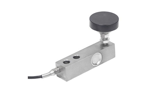
How to Choose a Load Cell in 12 Steps
A reliable selection process moves from the measurement objective to the mechanical structure, then to capacity, environment, electronics, calibration, and supplier documentation. Skipping an early step usually creates problems that cannot be corrected by software or recalibration.
Define What Must Be Measured
Weight, force, tension, compression, torque, or several force components
Start by defining the physical quantity and the purpose of the reading. A tank-weighing system, press-force monitor, crane overload device, laboratory test frame, robotic wrist sensor, and axle scale all measure mechanical load, but they require different sensor structures and acceptance criteria.
Determine whether the reading will be used for production control, inventory, safety monitoring, inspection, research, process batching, structural verification, or commercial weighing. A safety-related measurement may need redundancy or independent mechanical protection, while a process-control system may prioritize repeatability and integration with a controller.
- Identify the physical quantity being measured.
- Define whether the reading is continuous, periodic, or temporary.
- State whether the result controls equipment or only records data.
- Define the consequences of an incorrect reading.
- Separate force measurement from weight estimation where acceleration is present.
Confirm the Force Direction
Compression, tension, shear, tension-compression, torque, or multiple axes
A load cell must be selected for the direction in which force enters the sensor. Compression sensors measure pushing force. Tension sensors measure pulling force. S-type designs commonly measure both tension and compression. Shear beam structures detect controlled shear deformation, while multi-axis sensors separate forces and moments acting along several directions.
The actual force path is more important than the apparent movement of the machine. A vertical actuator may still introduce bending or lateral force if the fixtures are misaligned. A cable system may apply tension but also rotate the sensor. A platform may appear to apply compression while frame distortion introduces side loads.
Compresión
Common in tanks, silos, presses, platforms, truck scales, and structural supports.
Tensión
Common in cranes, suspended hoppers, cables, hoists, test machines, and lifting structures.
Multiple Axes
Common in robotics, structural testing, assembly validation, and force-control systems.

Calculate the Required Capacity
Gross load, dead load, uneven distribution, shock, overload, and support count
Rated capacity should be based on the maximum force that can reach each sensor, not only the expected net product weight. Include the weight of the platform, vessel, fixtures, mounting hardware, contained material, temporary process loads, uneven distribution, acceleration, impact, and maintenance conditions.
The result must then be adjusted for uneven load distribution, dynamic forces, structural geometry, and manufacturer recommendations.
The effective number of sensors may be lower than the physical number of supports when the structure is not rigid or when one corner can carry a larger share of the load. A four-point platform does not guarantee that each load cell receives exactly one quarter of the total force.
Do not choose capacity only from the normal operating value. A vessel may be filled beyond its normal level, a vehicle may brake on a weighing pad, a crane may experience shock loading, or a maintenance tool may apply force through one support.
Excessively high capacity can also be undesirable. A sensor operating at a very small fraction of its range may provide less useful signal for the required resolution. Capacity must therefore balance overload protection, usable output, structural safety, and measurement resolution.
Evaluate Static, Cyclic, and Dynamic Loading
Steady force, repeated cycles, impact, vibration, acceleration, or motion
Static capacity does not fully describe a dynamic application. A sensor used beneath a stationary tank experiences different stresses from a sensor in a press, packaging machine, vehicle weighing pad, crane, or robotic tool. Dynamic operation may create force peaks that are much higher than the average value.
- Define maximum loading and unloading speed.
- State the expected number of cycles.
- Identify impact, vibration, oscillation, or resonance.
- Describe acceleration, braking, or moving-load effects.
- Specify required sampling rate and response time.
- Confirm whether mechanical stops or overload protection are available.
Repeated loading also raises fatigue questions. The mechanical element, threaded connections, bolts, pins, fixtures, and supporting frame must withstand the expected cycle history. The load cell manufacturer should review dynamic projects using the complete operating profile rather than one maximum-force number.
Define Accuracy, Resolution, and Repeatability
Separate the sensor specification from complete-system performance
Accuracy should be defined in terms of the required result and operating conditions. Sensor datasheets may list nonlinearity, hysteresis, repeatability, creep, zero balance, temperature effect, and combined error. These values do not automatically equal the accuracy of the installed weighing or force-measurement system.
Complete-system performance also depends on the structure, mechanical alignment, mounting accessories, cable, junction box, amplifier, indicator, electrical noise, calibration method, temperature distribution, and the stability of the applied force.
Accuracy
Closeness of the measured result to the accepted reference under defined conditions.
Repetibilidad
Ability to produce similar readings when the same load is applied repeatedly under the same conditions.
Resolution
Smallest useful change that can be distinguished by the sensor, electronics, noise level, and display system.
A process batching system may value repeatability more than absolute laboratory accuracy. A structural test may require traceable calibration. A robotic control loop may prioritize bandwidth and cross-axis behavior. A commercial weighing system may have specific legal requirements in the destination market.
Select the Mechanical Load Cell Structure
Match the elastic structure to the force path and application
Load cell structure should be selected after the force direction, capacity, and installation geometry are known. Similar capacities can be supplied in very different mechanical formats, and those formats are not interchangeable.
| Load Cell Structure | Main Force Direction | Aplicaciones habituales | Selection Benefit | Installation Concern |
|---|---|---|---|---|
| De un solo punto | Compression through a platform | Bench scales, packaging, small platforms | One sensor can support a suitable platform | Platform size and off-center load limits |
| Viga de corte | Vertical loading producing shear | Tanks, hoppers, platforms, batching | Low-profile industrial installation | Mounting kit, side force, and base stiffness |
| Compression column | Compresión | Truck scales, silos, heavy platforms | Direct load path for substantial force | Alignment and structural movement |
| Tipo S | Tension and compression | Suspended hoppers, test machines, hanging loads | Bidirectional force measurement | Bending, twisting, and threaded alignment |
| Radio | Compression or bidirectional | Presses, testing, force control | Low profile and central loading | Flat surfaces and bolt-pattern control |
| Pasador de carga | Structural pin loading | Pulleys, cranes, clevis joints, shackles | Integrates into an existing pin location | Usually requires custom mechanical review |
| Arandela | Compression around a central hole | Bolt preload, clamping, fastening | Fits around a bolt or shaft | Bearing surface and force distribution |
| Capsule or miniature | Depends on internal structure | Compact machines, fixtures, embedded measurement | Small installation envelope | Cable clearance and load alignment |
| Multieje | Several forces or moments | Robotics, structural testing, control systems | Measures several load components | Calibration matrix and data integration |
Structure names and output names describe different features. A shear beam sensor may have analog or digital output. A miniature sensor may measure compression or tension. A stainless steel sensor may use a column, spoke, beam, pin, or another structure.
Check Installation Space and Mounting Geometry
Dimensions, force introduction, mounting surfaces, restraints, and access
The available installation envelope often determines whether a standard load cell can be used. Provide overall height, diameter, width, hole spacing, thread size, pin dimensions, flange pattern, cable exit direction, connector clearance, and access for tools or future replacement.
Mounting surfaces should be sufficiently flat, rigid, and aligned for the selected structure. Flexible plates, thin frames, uneven bases, loose bolts, unsuitable washers, and contact with surrounding equipment can change the load path.
- Provide a dimensioned installation drawing.
- Mark the intended force direction.
- Identify fixed and moving surfaces.
- Show all bolts, threads, pins, restraints, and supports.
- Allow clearance for cables and connectors.
- Review thermal movement of tanks and long structures.
- Confirm access for installation, calibration, and replacement.

Evaluate Side Loads, Bending, Torque, and Misalignment
Identify forces that are not part of the intended measurement axis
Parasitic loads are among the most common causes of unstable or inaccurate measurements. A load cell may be rated for a large axial force but remain sensitive to bending, side force, torque, eccentric loading, or contact with the surrounding structure.
Sources of Unwanted Load
- Misaligned threaded connections
- Rigid pipes attached to a weighing tank
- Platform contact with walls or guards
- Cable tension acting on a miniature sensor
- Thermal expansion of long frames
- Uneven foundation settlement
- Rotating shackles or pulley assemblies
Possible Controls
- Rod ends or alignment accessories
- Purpose-designed weighing modules
- Flexible pipe and cable connections
- Mechanical restraints with controlled clearance
- Self-aligning loading hardware
- Rigid and level mounting surfaces
- Independent overload and travel stops
Software correction cannot fully compensate for an unstable force path. Mechanical causes should be removed before calibration data are interpreted.
Select Material and Environmental Protection
Temperature, moisture, corrosion, dust, chemicals, washdown, and hazardous areas
Environmental selection should be based on the actual exposure at the sensor, connector, cable joint, amplifier, junction box, and indicator. A sealed load cell can still fail if water enters through a damaged cable or an unsuitable connector.
Temperature
Review operating range, temperature gradients, thermal cycling, nearby heat sources, and cable suitability.
Moisture and Washdown
Evaluate sealing, cable entry, connector, junction box, drainage, cleaning pressure, and immersion risk.
Corrosion and Chemicals
Match structural material, surface treatment, seals, cable jacket, and connector to the actual substances present.
Dust and Debris
Prevent material buildup from bridging the weighing structure or blocking the intended movement of mounting hardware.
Outdoor Installation
Consider rain, condensation, ultraviolet exposure, lightning, temperature change, flooding, and cable protection.
Hazardous Areas
Confirm the required classification, accepted approval, associated equipment, wiring method, and local installation rules.
The terms sealed, waterproof, corrosion-resistant, high-temperature, and explosion-proof are not interchangeable. Each describes a different requirement that must be verified against the project documentation.
Choose the Output Signal and Electronics
Raw analog, amplified, current, digital, serial, or wireless communication
Output selection depends on cable length, electrical noise, controller input, sampling rate, diagnostics, system architecture, and whether several sensors are combined. Mechanical load cell structure and output type should be selected independently.
| Output Arrangement | Typical Use | Advantages | Points to Confirm |
|---|---|---|---|
| Raw analog strain-gauge signal | Scales, test systems, external amplifiers | Direct sensor output and flexible instrumentation choice | Excitation, sensitivity, cable length, shielding, amplifier compatibility |
| Amplified voltage output | Machine control and data acquisition | Stronger signal for controller input | Supply voltage, output range, bandwidth, zero adjustment |
| 4–20 mA | Industrial process control and long cable runs | Common industrial current-loop interface | Loop supply, scaling, isolation, update rate, fault behavior |
| RS485 | Digital industrial networks and multiple devices | Digital communication and addressable devices | Protocol, baud rate, register map, termination, power supply |
| Wireless | Portable weighing, rotating equipment, difficult cabling | Reduced signal-cable installation | Power, range, interference, latency, pairing, data loss, battery service |
| Multi-channel digital system | Multi-axis sensors and synchronized force measurement | Coordinated acquisition of several components | Channel synchronization, calibration matrix, sampling, software interface |
Also specify the weighing indicator, amplifier, transmitter, controller, junction box, display, recording system, software, power source, and required communication documentation. A sensor output is only useful when the connected equipment can excite, read, scale, filter, and calibrate it.
Define Calibration and Traceability Requirements
Calibration direction, points, fixtures, documents, and installed-system checks
Calibration should reflect the intended direction and use of the sensor. A tension-compression sensor may require both directions. A multi-axis sensor may require individual axis calibration and information about cross-axis response. A complete platform or tank system may require calibration after installation because the supporting structure affects load distribution.
- Specify the required calibration direction.
- Define the force or weight range to be calibrated.
- State the number and distribution of calibration points.
- Confirm whether ascending and descending loading are required.
- Define the required traceability and documentation.
- Identify whether calibration is needed for the sensor or complete system.
- Plan recalibration intervals according to use and risk.
Calibration cannot remove mechanical interference. The installation should be inspected for contact, pipe forces, frame distortion, loose bolts, foundation movement, and cable problems before calibration adjustments are made.
Evaluate the Manufacturer and Production Controls
Engineering support, samples, inspection, documentation, and long-term supply
The manufacturer should be evaluated according to the technical demands of the project. A standard bench scale sensor may require only a verified datasheet and dimensional drawing. A custom load pin, multi-axis sensor, axle weighing pad, hazardous-area system, or safety-related lifting sensor requires deeper engineering and documentation.
Technical Review
- Application and force-path review
- Dimensional and mounting drawings
- Capacity and overload evaluation
- Signal and instrument compatibility
- Environmental suitability
- Sample and installation testing
Production Review
- Incoming material inspection
- First-piece confirmation
- Bonding, wiring, and sealing control
- Linearity and temperature checks
- Final calibration and identification
- Batch and shipment traceability
Buyers should also review lead time, minimum order quantity, prototype cost, expected annual volume, product-change control, replacement availability, calibration support, packaging, labeling, private-label requirements, and long-term model availability.
Which Load Cell Should Be Selected for Each Application?
Application-based selection provides a starting point, but the final sensor must still be checked against capacity, force direction, mounting, environmental exposure, required accuracy, signal output, and system architecture.
| Solicitud | Commonly Considered Load Cells | Reason for Selection | Main Installation Issues | Information to Confirm |
|---|---|---|---|---|
| Compact platform scale | De un solo punto | One sensor can support a suitably sized platform | Platform stiffness, size, and off-center loading | Platform dimensions, capacity, hole pattern, environment |
| Large industrial platform | Viga de corte Compresión | Multiple sensors distribute the platform load | Uneven loading, junction box, base stiffness | Support count, frame drawing, gross load, calibration |
| Tank or hopper weighing | Viga de corte Compression column Tipo S | Supported and suspended vessels require different force paths | Pipe forces, thermal expansion, restraints, wind | Dead load, product load, supports, pipes, environment |
| Crane or hoist | Tirante de tensión Pasador de carga Tipo S | Measures force within the lifting path | Shock, rotation, bending, safety factors | Connection drawing, peak force, dynamics, approvals |
| Press-force measurement | Radio Cápsula Compresión | Direct measurement beneath a compression point | Surface flatness, eccentric loading, impact | Force profile, speed, dimensions, cycle count |
| Material test machine | Tipo S Radio Tensión | Supports tension, compression, or bidirectional tests | Fixture alignment, bending, calibration direction | Test range, fixtures, accuracy, speed, calibration |
| Bolt or clamping force | Arandela Anular | Fits around a bolt, shaft, or tie rod | Bearing surfaces and preload distribution | Inner diameter, outer diameter, thickness, preload |
| Machine joint or pulley | Pasador de carga | Replaces or instruments an existing structural pin | Bearing positions, rotation, cable exit, locking | Original pin drawing, support spacing, load direction |
| Robótica | Multieje Miniatura | Measures several forces or fits a restricted envelope | Stiffness, cross-axis effects, cable routing | Axis ranges, moments, sampling, interface, dimensions |
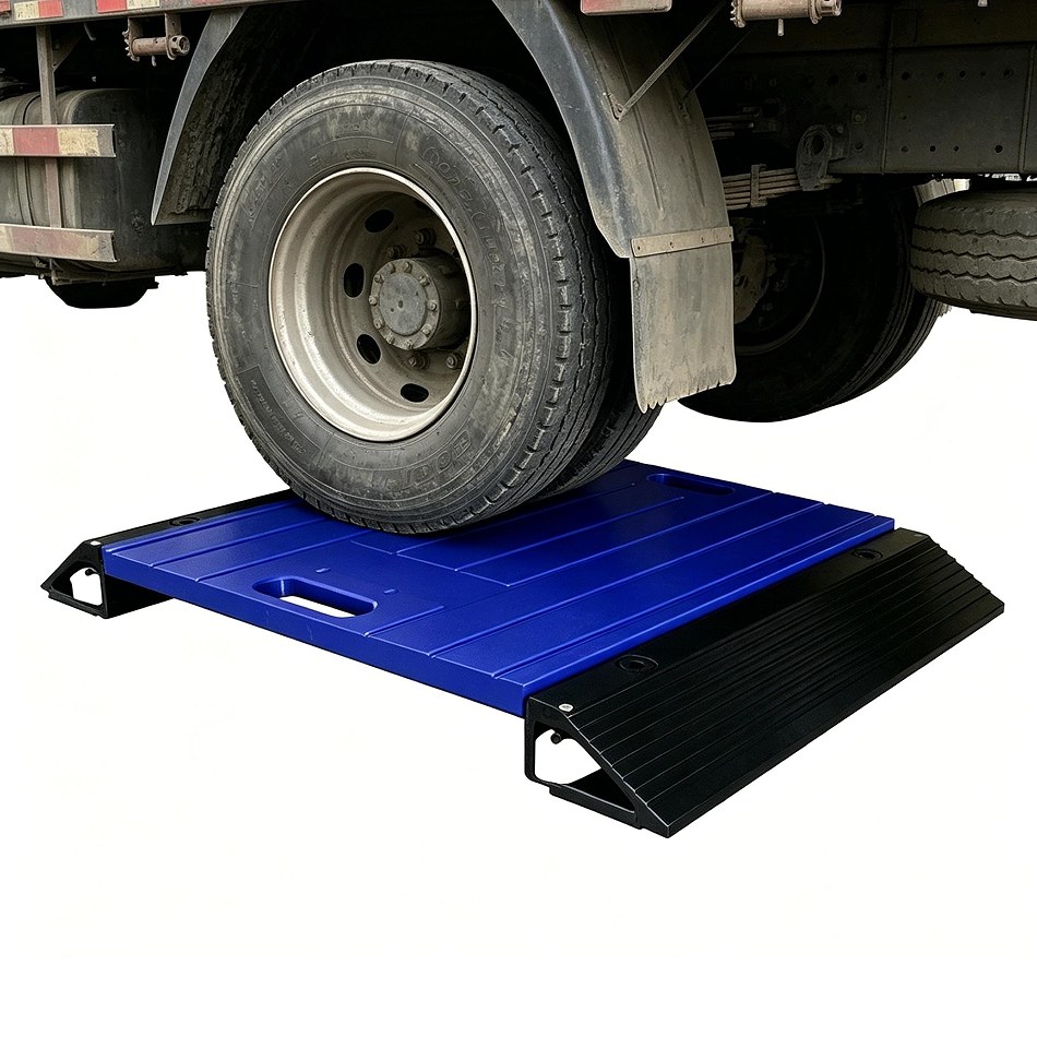
| Portable axle weighing | Integrated weigh pad sensors | Measures wheel or axle load in a portable platform | Tire position, ramps, surface level, motion | Vehicle type, axle load, static or dynamic use, display |


Common Mistakes When Choosing a Load Cell
Most selection failures result from incomplete application information rather than a defective sensing principle. The following errors should be corrected before a model is approved.
Choosing Only by Capacity
Capacity does not define force direction, structure, size, mounting, environment, accuracy, output, or dynamic behavior.
Ignoring Dead Load
Platforms, vessels, fixtures, cables, accessories, and mounting hardware may consume a large part of the available range.
Assuming Equal Load Distribution
Structural flexibility, uneven foundations, eccentric loading, and pipe forces can make one sensor carry more load than the others.
Using Datasheet Accuracy as System Accuracy
Installed performance also depends on mechanics, electronics, calibration, temperature, noise, and operating conditions.
Ignoring Side Force and Bending
An axial load cell can produce unstable readings or suffer damage when the surrounding structure introduces unwanted moments.
Selecting Output Too Late
The output must match cable length, controller input, sampling rate, electrical environment, protocol, and power supply.
Confusing Mechanical Type with Signal Type
Digital, RS485, 4–20 mA, and wireless describe signal systems rather than the mechanical structure of the sensor.
Ordering Before Reviewing Drawings
Dimensions, holes, threads, loading surfaces, cable exit, and access should be confirmed before a standard or custom model is approved.
What Information Should Be Sent to a Load Cell Manufacturer?
A technically complete request allows the manufacturer to evaluate the sensor structure, rated capacity, mechanical interface, environmental protection, electronics, testing, and production plan without relying on assumptions.
Measurement Information
- Application and equipment function
- Force direction
- Normal working load
- Maximum and shock load
- Static, cyclic, or dynamic operation
- Required accuracy and repeatability
- Sampling and response requirements
Mechanical Information
- Dimensioned installation drawing
- Available space
- Mounting holes, threads, pins, or flanges
- Loading surfaces
- Platform or support layout
- Expected side forces and moments
- Cable and connector clearance
Environmental Information
- Operating temperature
- Indoor or outdoor use
- Water, washdown, or immersion
- Dust, oil, or chemicals
- Corrosion exposure
- Vibration and shock
- Hazardous-area requirements
Electrical and Commercial Information
- Required output signal
- Supply or excitation voltage
- Cable length and connector
- Indicator, amplifier, or controller
- Communication protocol
- Prototype and batch quantities
- Required calibration and documents
Example request: “The sensor will measure compression beneath a four-point tank support. The drawing shows the available mounting height, support spacing, vessel dead load, maximum material load, pipe connections, operating temperature, washdown conditions, cable route, 4–20 mA output requirement, indicator model, prototype quantity, and expected annual volume.”
Asistencia técnica para células de carga y sistemas de pesaje a medida
Ningbo SAINTBOND Intelligent Technology Co., Ltd. supplies load cells, force sensors, multi-axis sensors, tension sensors, portable axle scales, weigh-in-motion systems, crane scales, industrial scales, and weighing indicators. Its load cell portfolio covers compression column, shear beam, S-type, spoke, tension, pin-type, bellows, bridge, capsule, miniature, washer, explosion-related, and single-point structures.
Project evaluation can include capacity, structural dimensions, mounting layout, material, cable, connector, signal output, weighing indicator, junction box, communication method, and software-interface requirements. Available signal arrangements can include analog, digital, RS485, 4–20 mA, and wireless configurations according to the project.
Revisión de los requisitos
Review application, capacity, force direction, environment, dimensions, signal output, and quantity.
Engineering Evaluation
Evaluate mechanical structure, 3D model, circuit adaptation, mounting, cable, connector, and accessories.
Sample Testing
Prepare samples for installation review, calibration, signal stability, and equipment-side verification.
Production Control
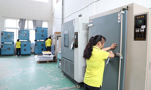
Apply material inspection, process checks, final calibration, identification, and shipment traceability.
Prepare a Load Cell Project for Technical Review
Send the application, force direction, capacity, dimensions, environment, output signal, quantity, and equipment drawing for product matching or custom evaluation.
Visita SAINTBOND Send Project RequirementsFrequently Asked Questions About Choosing a Load Cell
What is the first step in choosing a load cell?
The first step is to define what must be measured and how force reaches the sensor. State whether the application measures compression, tension, shear, clamping force, weight, torque, or several force components, and explain how the reading will be used.
How do I calculate load cell capacity?
Begin with the maximum gross system load, including dead load, product, fixtures, platforms, temporary loads, and dynamic forces. Divide the adjusted maximum by the effective number of sensors, then account for uneven distribution, shock, overload, and manufacturer recommendations.
Should I choose a higher-capacity load cell for safety?
Additional capacity can provide overload margin, but an excessively large range may reduce useful signal for the required resolution. Capacity should balance maximum possible force, uneven distribution, dynamics, structural protection, sensitivity, and measurement requirements.
What load cell is suitable for a platform scale?
A single-point load cell is commonly used for a compact platform supported by one sensor. Larger platforms often use several shear beam or compression sensors. Platform dimensions, frame stiffness, off-center loading, support geometry, environment, and calibration must be reviewed.
What load cell is commonly used for tank weighing?
Shear beam and compression load cells are commonly used for supported tanks, while S-type sensors may be used for suspended vessels. The choice depends on tank weight, support count, pipe forces, thermal movement, wind, vibration, environment, and available mounting space.
What is the difference between analog and digital load cells?
An analog load cell provides an electrical signal that requires suitable excitation and signal conditioning. A digital load cell includes signal conversion or communication electronics. Digital and analog describe output arrangements, not the mechanical shape of the sensor.
When should a 4–20 mA load cell be considered?
A 4–20 mA arrangement may be considered for industrial process control, long cable runs, and controllers designed for current-loop inputs. Confirm loop power, scaling, isolation, response rate, electrical noise, fault behavior, and whether the transmitter is integrated or external.
When is a multi-axis load cell required?
A multi-axis load cell is required when one axial value cannot describe the complete mechanical load. Robotics, structural testing, force-control systems, assembly validation, and research equipment may need separate force and moment measurements along several defined axes.
Why can a correctly rated load cell still produce unstable readings?
Unstable readings may result from side force, bending, platform contact, flexible mounting, pipe loads, thermal movement, loose bolts, poor grounding, electrical noise, water entry, damaged cables, unsuitable filtering, or an incorrect calibration procedure.
Does load cell datasheet accuracy equal system accuracy?
No. Datasheet values describe the sensor under specified test conditions. Installed-system accuracy also depends on the supporting structure, mounting hardware, load distribution, cable, electronics, temperature, electrical noise, calibration, and operating environment.
When is a custom load cell necessary?
A custom load cell may be necessary when a standard model cannot match capacity, dimensions, force direction, mounting holes, threads, pin geometry, material, cable exit, connector, environmental conditions, signal output, calibration, or production integration.
What drawing should be sent to a load cell manufacturer?
Send a dimensioned equipment drawing showing the sensor location, force direction, available space, mounting surfaces, holes, threads, pins, supports, moving parts, cables, connectors, surrounding components, and all structures that can introduce side force or restrict movement.
Final product selection should be reviewed against the complete application, mechanical structure, expected force profile, environmental requirements, connected electronics, calibration method, and applicable project documents.
¿Necesitas básculas de eje portátiles, células de carga industriales, sensores de fuerza, indicadores de pesaje y sistemas de medición dinámica? ¿Buscas soluciones para tu proyecto?
Disfruta de precios directos de fábrica y de asistencia técnica por parte de nuestros expertos en un plazo de 24 horas.
Solicita un presupuesto rápido English
 Arabic
 Russian
 Portuguese
 Spanish
 Japanese
 German