

100kg Load Cell Arduino: Application Fit Checks
Reference Standard: Relevant load-cell electrical and performance documentation. The available LCX6013 catalog establishes sensor specifications and interface options, but it does not establish an Arduino- or HX711-specific connection standard.
100kg Load Cell Arduino Starts With the Measurement Need
A 100kg load cell Arduino project should not begin by choosing code or an amplifier. First determine whether the application needs one-direction weight measurement or simultaneous force and moment measurement across multiple axes, because the verified LCX6013 is a six-axis sensor rather than a typical single-axis weighing device.
The catalog documents LCX6013 characteristics and several output routes, but it does not state Arduino or HX711 compatibility.
A search for a 100kg load cell often sounds simple: select a 100kg sensor, connect it to a controller, calibrate it, and read a number. That approach can work only when the measurement problem itself is simple.
The more important first question is what physical quantities must be measured.
A basic weighing application may need only the load acting in one intended direction. Examples can include a platform, container, test fixture, or suspended object where the system ultimately needs one force or weight value.
A multi-axis measurement problem is fundamentally different. A robot fixture, force-feedback experiment, assembly tool, or interaction test may need to distinguish loads coming from different directions and may also need information about moments around those directions.
In that situation, selecting a sensor only because its specification includes 100kg can lead to the wrong architecture. Capacity describes only one part of the requirement. The number of measurement axes, force directions, moment requirements, mechanical interface, electrical output, and controller path all matter.
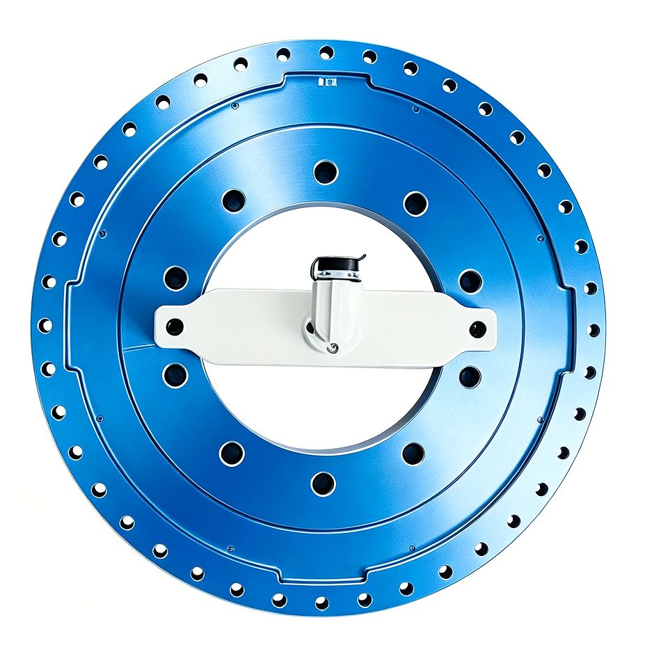
That distinction is especially important for the LCX6013 because the catalog identifies it as a Multi-Axis Load Cell / Six-Axis Load Cell.
Why the LCX6013 Is Different From a Single-Axis Weighing Sensor
The LCX6013 technical table lists Fz=Fy=Fx capacity as 100kg. It also lists Mx=My=Mz as 2kg. Those values belong to the documented LCX6013 configuration and should not be generalized to every sensor described by a “100kg load cell” search.
The practical distinction is measurement architecture.
A single-axis weighing setup is normally organized around one primary load direction. Its mechanical design, calibration process, signal interpretation, and controller logic can therefore focus on one intended measurement quantity.
The LCX6013 is documented for multiple force and moment dimensions. Its product information also describes a structural decoupling design with small coupling between dimensions. In practical terms, the application is intended to obtain information from several loading components instead of reducing the measurement problem to one value.
That changes the controller discussion.
The catalog lists 0.5-2.0mV/V output sensitivity and 3-10V excitation voltage for this model. A millivolt-per-volt specification indicates that electrical planning must consider the relationship between sensor excitation and output signal level. It does not, by itself, prove compatibility with any particular development board.
The LCX6013 documentation also states that analog output can be used with a collector and lists 485, CAN, USB, Ethernet, and EtherCAT among available interface options. These are important because they show that there is more than one possible route for taking measurements from the sensor system to downstream electronics.
They do not establish that one of those routes connects directly to an Arduino.
Likewise, the presence of an analog-output option does not establish HX711 compatibility. The HX711 is commonly associated with load-cell projects, but the provided LCX6013 documentation does not name it, provide a wiring diagram for it, or specify an Arduino library.
This evidence boundary matters because a successful measurement system depends on matching several layers:
- the physical quantities being measured;
- the selected LCX6013 output or interface configuration;
- the required excitation and signal handling;
- the number of measurements the application must acquire;
- the controller’s electrical and communication capabilities;
- any additional conditioning, conversion, or communication hardware.
Treating all 100kg sensors as interchangeable can hide these differences.
The LCX6013 catalog also documents 0.1-0.5%F.S comprehensive accuracy, 0.3%F.S nonlinearity, 0.3%F.S lagging, and 0.3%F.S repeatability. These values describe the catalog-listed model, but they do not answer whether a particular Arduino-based acquisition chain can preserve or interpret the signals correctly. Sensor performance and controller compatibility remain separate questions.
Signs the Project Definition Is Still Incomplete
- The design specifies “100kg” but does not define which force directions or moments must be measured.
- The controller has already been selected even though the LCX6013 output or communication configuration has not been confirmed.
- The plan assumes an HX711 or direct Arduino connection without a documented electrical or interface match.
When a Six-Axis 100kg Sensor Fits an Arduino-Oriented Project
A six-axis sensor becomes relevant when the project needs information that one-direction weighing cannot provide.
Consider a fixture that experiences a vertical force while also receiving lateral forces. If the application must distinguish those components instead of seeing only a combined response, multi-axis measurement becomes valuable. The same applies when the project must observe forces and moments during robot interaction, tooling contact, mechanical testing, or automation development.
In those situations, an Arduino-class controller might still be part of the larger system, but the controller should be treated as a downstream processing choice, not as proof that a particular sensor is compatible.
The LCX6013 documentation gives several verified characteristics that should shape that decision.
Its excitation range is 3-10V, while the documented sensitivity is 0.5-2.0mV/V. These specifications mean that an analog configuration requires deliberate signal-path planning. The controller-side design must determine how the chosen sensor output is conditioned, acquired, converted, and interpreted.
Alternatively, a project may investigate one of the listed communication-interface configurations. The catalog identifies 485 / CAN / USB / Ethernet / EtherCAT support, but it does not identify which hardware modules, protocol implementation, data format, or software library would be required for an Arduino environment.
That distinction prevents a common engineering mistake: confusing the existence of an interface with a complete controller integration.
A system can support CAN, for example, while still requiring a suitable transceiver, protocol definition, message mapping, configuration procedure, and application software. Similar questions apply to 485 or other communication routes. The catalog evidence confirms the interface choices; the implementation details must be confirmed for the exact configuration being purchased.
The mechanical environment also deserves attention. The LCX6013 table documents a -20°C to +80°C operating temperature range and IP65 degree of protection for the sensor. Those ratings belong to the sensor itself.
They should not be extended to an Arduino board, amplifier, converter, connector, power supply, enclosure, or other electronics. If the complete measurement system will operate in dust, moisture, temperature variation, or an industrial enclosure, every component needs its own environmental assessment.

The core application-fit test is therefore straightforward:
Choose the six-axis measurement concept because the application needs six-axis information, not merely because the keyword contains “100kg.”
If the project ultimately needs only one weight or force value, a multi-axis sensor may introduce measurement channels and integration requirements that the application does not need. If the project genuinely needs forces in several directions plus moment information, then the LCX6013 measurement architecture deserves consideration before the controller interface is finalized.
Confirm the Controller Connection Before You Build
Once the measurement requirement is clear, integration can be reduced to four focused verification tasks.
1. Confirm the Exact LCX6013 Output Configuration
Do not begin from the assumption that every LCX6013 is delivered with the same downstream connection.
The documentation describes analog output and multiple communication options. Before designing electronics or writing software, confirm which output or interface configuration applies to the specific sensor being considered.
That confirmation determines the next engineering questions. An analog path requires attention to excitation, signal level, acquisition, and conditioning. A communication-interface path requires compatible physical-layer hardware and a defined method for interpreting transmitted measurements.
The key objective is not to force the sensor into an existing Arduino circuit. It is to identify the documented sensor output first and build the downstream system around verified requirements.
2. Define the Measurements the Application Will Actually Use
List the force and moment quantities required by the project.
The LCX6013 is documented with Fx, Fy, Fz force capacities and Mx, My, Mz entries. A project that genuinely needs several of these components must plan how each required measurement will be acquired, mapped, calibrated, and processed.
If only one measurement is useful to the application, revisit whether a six-axis architecture is necessary.
This prevents the controller design from becoming more complex than the measurement problem.
3. Match Electrical and Communication Requirements
Compare the selected sensor configuration with the actual controller hardware.
For an analog route, confirm excitation requirements, expected signal characteristics, acquisition hardware, input range, resolution needs, grounding, wiring, and whether additional signal conditioning is necessary.
For a communication route, confirm the physical interface, communication hardware, protocol details, data representation, update behavior, and software requirements.
Do not infer these details from the interface name alone.
The provided catalog establishes that the LCX6013 has documented interface choices. It does not establish a ready-made Arduino load cell code package, direct Arduino pin assignment, or HX711 wiring method.
4. Verify the Complete System, Not Just the Sensor
A working measurement chain includes more than the load cell.
Mechanical mounting, excitation or power hardware, connectors, cabling, acquisition electronics, communication converters, controller inputs, software, calibration, and environmental protection all contribute to whether the system works as intended.
The LCX6013 documentation lists IP65 protection and an operating temperature range of -20°C to +80°C, but those specifications cannot automatically be assigned to the rest of the measurement chain.
Before finalizing the build, verify every component against its actual operating environment and interface role.
Items to Confirm Before Choosing the Controller Path
- Define whether the project needs one force value or multiple force and moment measurements.
- Confirm the exact LCX6013 output or communication-interface configuration.
- Verify the documented 3-10V excitation requirements where relevant.
- Determine how the 0.5-2.0mV/V output specification will be handled if using an analog configuration.
- Confirm the controller’s electrical or communication interface requirements.
- Identify any required amplifier, data-acquisition device, transceiver, converter, or communication hardware.
- Request confirmed protocol, wiring, channel, and data-format information for the selected configuration.
- Do not assume Arduino or HX711 compatibility unless it is explicitly documented for the chosen setup.
- Check environmental requirements separately for the sensor and every downstream electronic component.
- Plan calibration and software interpretation only after the physical and electrical architecture is defined.
For application-specific confirmation, the safest next step is to discuss the required force directions, moment measurements, output configuration, and controller interface with Ningbo SAINTBOND Intelligent Technology Co.,Ltd., which is presented in the available documentation as a China load cell and force sensor manufacturer with industrial and multi-axis force measurement products. Its broader load cell and force sensor portfolio provides the appropriate context for confirming product and interface details.
The important boundary remains unchanged: the available LCX6013 documentation verifies its sensor characteristics and interface options, but it does not establish a specific Arduino- or HX711-ready configuration.
Frequently Asked Questions (FAQ)
How does a load cell work?
A load cell converts applied mechanical loading into an electrical measurement that downstream electronics can acquire and interpret. For the LCX6013, the catalog documents multi-axis force and moment measurement, 0.5-2.0mV/V sensitivity, and multiple output/interface options. The exact controller connection depends on the selected configuration.
How can I check a faulty load cell in an Arduino project?
Separate the sensor from the controller assumption. Verify excitation, wiring, unloaded output behavior, response to controlled loading, and the selected acquisition or communication path. For the LCX6013 specifically, troubleshooting should use the confirmed output configuration because the catalog does not provide an Arduino- or HX711-specific diagnostic procedure.
Need portable axle scales, industrial load cells, force sensors, weighing indicators, and dynamic measurement systems. Solutions for Your Project?
Get factory-direct pricing and technical support from our experts within 24 hours.
Request a Quick Quote English
 Arabic
 Russian
 Portuguese
 Spanish
 Japanese
 German